Prototyping Artificial Muscles with Silicone and Iron Powder
During the June-July 2023 Oberlin College Research Fellowship, I worked with Prof. Patrick Simen to test whether cast silicone–iron composites could support a low-cost, muscle-inspired soft actuator. Across eight weeks, I moved from literature review and CAD to mold fabrication, material-ratio experiments, and magnetic-field measurements. The result was a repeatable prototyping method and a clearer experimental question—not yet a finished artificial muscle.

Research question
Soft robotics replaces rigid links with compliant structures that can deform around people and irregular objects. The literature includes pneumatic systems, dielectric elastomer actuators, magnetically controlled elastomers, and many hybrid approaches (Hines et al., 2017; Chung et al., 2021). My project focused on a narrower fabrication question:
Can a pourable Dragon Skin™ silicone and iron-powder mixture be molded into a flexible structure that responds usefully to magnetic forces, while remaining simple to fabricate with desktop 3D printing?
The working hypothesis was that a reusable mold and tunable iron loading could provide a practical rapid-prototyping route. The quantitative work therefore measured how core material, coil current, sensor position, and iron-to-silicone mass ratio changed magnetic flux density. The iron ratio is defined as iron-powder mass divided by the combined mass of silicone parts A and B.
From CAD to measurement
The workflow combined Rhino and SolidWorks for CAD, fused-deposition modeling for the molds, and a benchtop magnetic-field test. This use of additive manufacturing followed the low-cost, fast-iteration approach described in soft-robotics manufacturing reviews (Gul et al., 2018; Schmitt et al., 2018).
Model muscle-, coil-, spring-, and permanent-magnet concepts in CAD.
FDM-print two-part molds and fit the halves before casting.
Weigh equal silicone parts, add the target iron mass, and mix to an even consistency.
Fill and clamp the mold, cure the silicone, demold, and trim flash with an X-ACTO knife.
Wind the test coil, fix the meter at 1 or 8 mm, sweep current, and record flux density.
The experiments used 5 Ω test coils, a fixed jig for sensor spacing, and both north- and south-side readings where available. Prototype records also tracked the two silicone masses, iron-powder mass, final part mass, visible bubbles, and demolding defects.
Prototype gallery


What the measurements show
Core material dominated the coil response
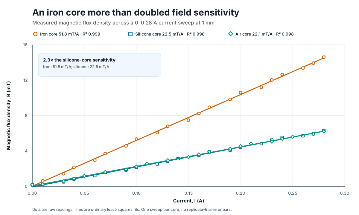
The first comparison held the geometry at a 1 mm sensor distance and swept current from 0 to 0.28 A. Ordinary least-squares fits show an iron-core sensitivity of 51.77 ± 0.81 mT/A (95% fit interval), compared with 22.47 ± 0.53 mT/A for silicone and 22.13 ± 0.43 mT/A for air. At the highest recorded current, the iron-core field reached 14.61 mT.
The silicone–iron mixture did not improve monotonically
For each mixture, I fitted the slope of magnetic flux density versus current. Among the complete 1 mm sweeps from ratios 0.00 to 0.86, the pure-silicone specimen produced the strongest south-side response and a near-strongest north-side response. Adding iron sometimes reduced the response, especially near the 0.50 ratio. A plausible explanation from the final reflection is that dispersed particles did not create a continuous high-permeability path; however, particle distribution was not imaged or otherwise characterized, so this remains a hypothesis.
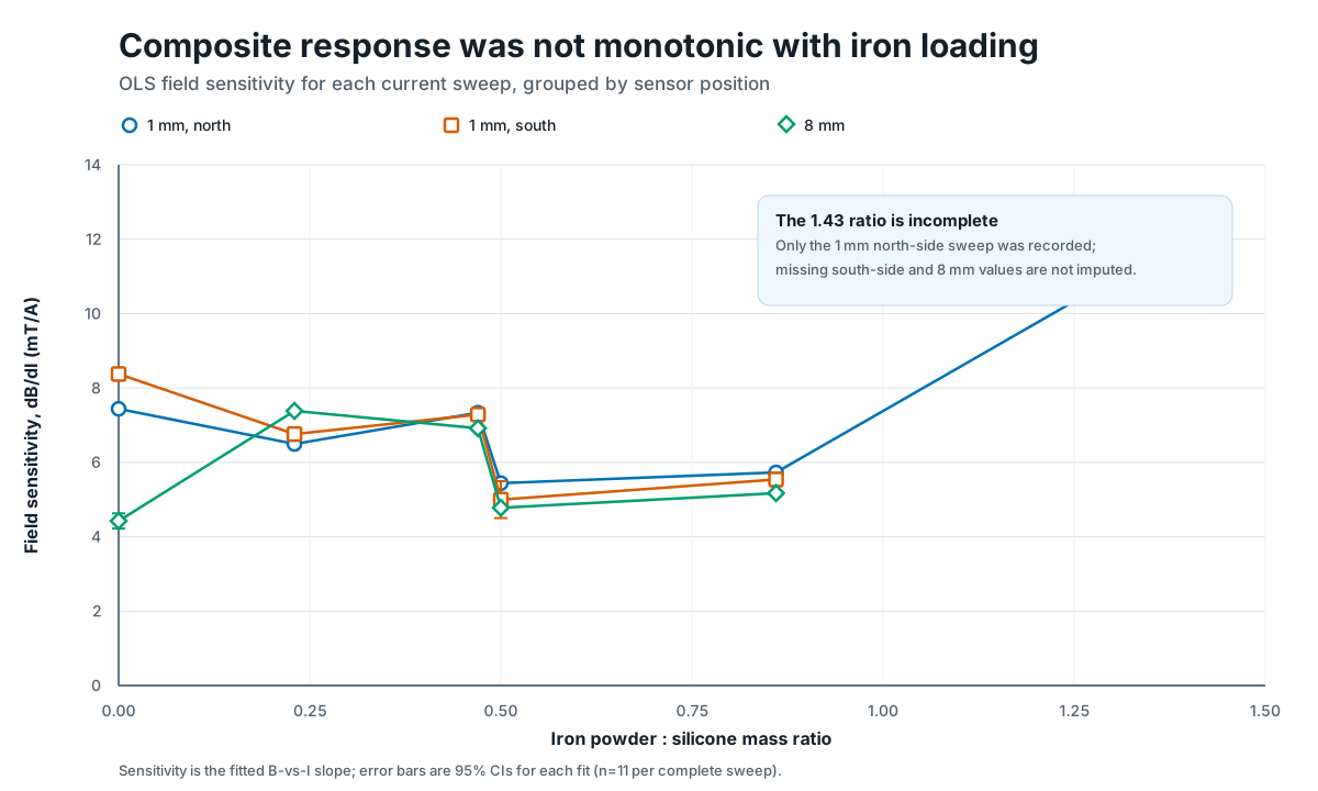
Within each sweep, flux density increased almost linearly with current (fit R² values were generally above 0.98).
A solid iron core increased fitted field sensitivity by about 2.3× compared with silicone, while air and silicone behaved similarly.
Low-to-moderate iron loading did not consistently increase the measured field; geometry, particle arrangement, and pole orientation also mattered.
The castings could be manipulated with permanent magnets, but this study did not yet quantify actuator stroke, blocking force, lifetime, or efficiency.
How to read these plots: the intervals quantify uncertainty in each linear fit, not manufacturing repeatability. The workbook contains one sweep per configuration, some incomplete conditions, and no randomized repeated specimens. The results are best treated as an engineering screen that identifies the next controlled experiment.
Setbacks and how I addressed them
As part of the fellowship, I was responsible to write weekly reflections and it showed to me that much of the research value came from resolving practical failures rather than following a clean linear plan.
CAD work was slower than expected
Rhino tool behavior delayed the first mold, and some shapes were faster to build in SolidWorks.
Response: Prof. Simen helped complete the blocked feature, and I adopted a hybrid Rhino–SolidWorks workflow so files could still be exchanged while I used the faster tool for each operation.
Filament repeatedly clogged the printers
Two Robotics Club printers jammed with the purchased PLA, halting the first mold and consuming much of weeks two through four.
Response: I learned the cold-pull procedure, traced recurring clogs to moisture-sensitive filament, improved storage, repaired one printer, and used mentor-printed molds as a temporary fallback.
Several parts would not demold cleanly
Two of three early prototypes failed or were difficult to remove, and the first compressed geometry became too stiff for the intended motion.
Response: I revised wall placement and cavity geometry, considered split-cylinder molds, and treated demolding and compliance as design constraints rather than post-processing problems.
Geometry defeated the magnetic concept
The fourth design left its rigid plates too far apart for strong attraction; the fifth design's small holes produced substantial mold imperfections.
Response: I changed plate spacing and magnet sizes, then made five iterations of the fifth design to determine which openings produced the cleanest mold.
The magnet-holder material created its own problem
An early holder was accidentally cast with the iron-filled mixture, magnetizing surfaces that needed to remain easy to assemble.
Response: I separated structural holders from responsive material and recast the test piece without iron so the magnets could be inserted predictably.
The final data challenged the hypothesis
Several silicone–iron mixtures generated a weaker field than pure silicone, contrary to the expected material trend.
Response: I preserved the result, discussed alternative explanations with my mentor, added the concentration plots to the presentation, and framed particle continuity as a testable next hypothesis.
Paper review
As another delivarable of the fellow, I did a review focused on Cao, Gao, and Conn’s magnetically coupled dielectric elastomer actuator. Their device used two parallel conical membranes that could be driven separately by changing the phase difference between electrical inputs. The paper reported 14% compression and 8.3% expansion, making it directly relevant to my interest in magnetic repulsion and spring biasing even though my prototypes used a different actuation architecture.
Why it mattered to this project: the paper showed how a magnetic coupling can alter the displacement of a compliant actuator and how force–displacement analysis can connect material behavior to mechanism design.
What the paper did well
- Compared permanent-magnet and linear-spring biasing through a systematic force analysis.
- Allowed the two membranes to be activated separately by changing phase, rather than forcing both cones to move together.
- Provided energy approximations, passive force–displacement tests, and statistical analysis to support the mechanism.
What I would have liked to see
- A stronger justification or optimization study for the stated 0.375 magnet-to-membrane diameter ratio.
- More discussion of failure modes, material alternatives, manufacturing difficulty, and practical design limits.
- Clearer photographs or visual measurements of expansion and contraction; the intended displacement was difficult to judge even with the supplemental material.
What I would test next
- Repeat each condition across independently cast specimens to separate regression fit uncertainty from manufacturing variability.
- Complete the missing 1.43-ratio conditions and test additional high loadings before drawing a composition trend.
- Control particle distribution with a documented mixing, degassing, and curing protocol, then inspect cross-sections to test the particle-continuity hypothesis.
- Measure mechanical performance—stroke, blocking force, response time, hysteresis, temperature, and cycle life—rather than using magnetic field alone as a proxy for actuator quality.
- Model the magnet-force and spring-force curves versus distance to identify stable regions where magnetic attraction can overcome elastic restoring force, an idea developed with Prof. Simen during week seven.
References
The project bibliography combined soft-actuator design, magnetically controlled elastomers, additive manufacturing, and general manufacturing texts. Citations used directly on this page are expanded below; the full research reading list is preserved for context.
Show the complete project bibliography
- Cao, C., Gao, X., & Conn, A. T. (2019). A compliantly coupled dielectric elastomer actuator using magnetic repulsion. Applied Physics Letters, 114(1), 011904. https://doi.org/10.1063/1.5071439
- Chung, H., Parsons, A. M., & Zheng, L. (2021). Magnetically controlled soft robotics utilizing elastomers and gels in actuation: A review. Advanced Intelligent Systems, 3(3), 2000186. https://doi.org/10.1002/aisy.202000186
- Berselli, G., Vertechy, R., Vassura, G., & Parenti-Castelli, V. (2011). Optimal synthesis of conically shaped dielectric elastomer linear actuators: Design methodology and experimental validation. https://doi.org/10.1109/TMECH.2010.2090664
- Gul, J. Z., Sajid, M., Rehman, M. M., Siddiqui, G. U., Shah, I., Kim, K., Lee, J., & Choi, K. H. (2018). 3D printing for soft robotics—A review. Science and Technology of Advanced Materials, 19(1), 243–262. https://doi.org/10.1080/14686996.2018.1431862
- Hines, L., Petersen, K., Lum, G. Z., & Sitti, M. (2017). Soft actuators for small-scale robotics. Advanced Materials, 29(13), 1603483. https://doi.org/10.1002/adma.201603483
- Shintake, J., Rosset, S., Schubert, B. E., Floreano, D., & Shea, H. R. (2015). A foldable antagonistic actuator. https://doi.org/10.1109/TMECH.2014.2359337
- Nguyen, C. T., Phung, H., Nguyen, T. D., Jung, H., & Choi, H. R. (2017). Multiple-degrees-of-freedom dielectric elastomer actuators for a soft printable hexapod robot. Sensors and Actuators A: Physical, 267, 505–516. https://doi.org/10.1016/j.sna.2017.10.010
- Schmitt, F., Piccin, O., Barbé, L., & Bayle, B. (2018). Soft robots manufacturing: A review. Frontiers in Robotics and AI, 5, 84. https://doi.org/10.3389/frobt.2018.00084
- Tang, X., Li, H., Ma, T., Yang, Y., Luo, J., Wang, H., & Jiang, P. (2022). A review of soft actuator motion: Actuation, design, manufacturing and applications. Actuators, 11(11), 331. https://doi.org/10.3390/act11110331
- Whitesides, G. M. (2018). Soft robotics. Angewandte Chemie International Edition, 57(16), 4258–4273. https://doi.org/10.1002/anie.201800907
- Groover, M. P. (2010). Fundamentals of modern manufacturing: Materials, processes, and systems (7th ed.). Wiley.
- Laschi, C., Rossiter, J., Iida, F., Cianchetti, M., & Margheri, L. (Eds.). (2018). Soft robotics: Trends, applications and challenges. Springer International Publishing.